What an amazing difference


.
Here is something I found out about this
US company - note the date!
SPECIFICATIONS OF PATENTS—DECEMBER 22,
1874157,913. CENTER-PINIONS FOR WATCHES.
Dietrich Gruen, Delaware, Ohio. [Filed June 12, 1874]
To all whom it may concern;
Be it known that I, DIETRICH GRUEN, of the town of Delaware, in the county of Delaware and the State of Ohio, have invented new and useful Improvements in Center-Pinions for Watches; and I do hereby declare that the following is a full, clear, and exact description thereof, reference being had to the accompanying drawings and to the letters of reference marked thereon, making a part of this specification.
My invention has for its object to provide against the injury to the train of wheels in a watch in case the mainspring breaks or becomes otherwise detached, so that the train will not receive the shock caused by the recoil when the spring gives way.
The nature of my invention consists in the shaft of the center-pinion being provided with a screw-thread, upon which works a collet, which is also provided with a corresponding screw-thread, in combination with a small spring and slot made in the pinion-wheel, in which said slot or groove works a corresponding bar or rib, which is rigidly secured to the said movable collet.
To enable others skilled in the art to make and use my invention, I will proceed to describe its construction and operation.

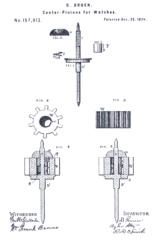
Figure 1 represents, in elevation, the shaft of a center-pinion of a watch, showing a screw-thread. Fig. 2 represents, in plan, the center-pinion. Fig. 3 is a side elevation of the pinion-wheel detached from the shaft. Fig. 4 is a vertical central section of my improvement in operative position. Fig. 5 is a vertical central section of my improvement when out of gear. Fig 6 is an elevation of screw-nut. Fig. 7 is an elevation of the collet. Fig. 8 is an elevation of the spring.
Letters of like name and kind indicate like parts in each of the figures. H represents the shaft upon which the center-pinion of a watch is placed. P represents a screw-thread, which commences near the top of the shaft, and extends downward to about the middle of the pinion, more or less, when the pinion is in its position upon the shaft. Below this screw-thread the shaft is made smaller in diameter, so as to allow the collet B to work freely upon the shaft when it has been run down off the screw thread, at which time it becomes so disengaged that no power or motion is transmitted to the train. This screw-collet is provided with a rib or bar, q, which fits closely but loosely in the slot or groove r in the pinion-wheel W. S shows a spring, which is secured to the shaft H in such a manner as to act upon the screw-collet. (Shown in Fig. 5.) N represents a screw-nut, which secures all the parts of my invention in their proper positions.
The operation of my invention is simple and may be readily understood. When the pinion-wheel is turned to the right it will be seen that by the action of the spring S the screw collet is forced up and becomes engaged with the screw-thread on the shaft, and at the same time the screw-collet is carried up and becomes engaged with the screw-nut, and thus becomes rigid with the shaft sufficiently to impart motion to the whole mechanism of the watch for keeping time. In case the mainspring breaks or becomes otherwise detached the action is reversed, at which time the collet runs down off of the thread on the shaft, the pinion is carried along from the barrel by the recoil of the spring, and so brings down the screw-collet below the thread, which gives it entire looseness, so as to relieve the strain upon the train.
It is well known that many watches are made for which no provision is made for the protection of the train of wheels against the recoil of the mainspring in case it breaks or becomes detached. In such a case the whole force of the recoil is brought upon the train so suddenly that it is not able to resist it, and the consequence is that very often many of the teeth or pivots are broken and the watch greatly damaged. By my invention this difficulty and danger is entirely obviated; besides, in case the mainspring breaks, a new one can be replaced without the necessity of taking the watch apart.
Having thus described my invention, what I claim as new, and desire to secure by Letters Patent of the United States, is—
The shaft H, provided with a screw-thread, P, spring S, in combination with a movable screw-collet, B, and pinion W, substantially as herein shown and described, and for the purposes set forth.
DIETRICH GRUEN.
Witnesses:
Geo. C. Eaton
D.H. Potter
[ 1867 | 1894 | 1904 | 1917 | 1921 | 1922 | 1929 | 1940 ]
[ Contents | Intro | Sources | Links | FAQ | Patent | Cover ]
Copyright © 1999-2001 Paul Schliesser contact
(I have contacted Paul Scliesser for permission to reproduce this information)
Further information available at:
www.pixelp.com/gruen/index.html 


